A network that has only four terminals, i.e. a pair of input terminals (the input port) and a pair of output terminals (the output port). The behaviour of a two-port network is usually described by the impedances presented at its terminals at specified frequencies. If the electrical properties are unchanged when the input and output ports are reversed the two-port network is symmetric; otherwise it is asymmetric. The network is described as balanced if its electrical properties are unchanged when both the input and output ports are interchanged simultaneously; otherwise it is unbalanced.
A very common arrangement, used particularly for attenuators and filters, is a ladder network consisting of a number of series and shunt impedances (Fig. a). This arrangement may be broken down for analysis into identical sections each with the same characteristic impedance. In order to avoid power dissipation in the load by reflections, a ladder network must be terminated by an impedance equal in value to the iterative impedance of the sections. The ladder filter shown in Fig. a may be analysed as a series of T-sections (Fig. b) terminated in the iterative impedance ZT. The same network may be considered as a series of π-sections (Fig. c.) that must be terminated in the iterative impedance Zπ. Comparison of the two shows that the half-section or L-section (Fig. d) acts as an impedance transformer from Zπ to ZT. Such half-sections may be used to match a two-port network to a load; they are especially important when composite networks are being designed. It can be shown that if the impedances used in the ladder are Z1 and Z2, as shown in Fig. b, then
In general Z1 and Z2 and hence ZT and Zπ will be dependent on frequency. If the product ZTZπ is substantially independent of frequency the network is a constant-R network.
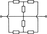
Other arrangements of elements used to form ladder filters or attenuators are the O-network, H-network, bridged-T, bridged-H, and twin-T networks, which are shown in Figs. e, f, g, h, and i.
(a) Generalized ladder filter
(b) T-section
(c) π-section
(d) L-sections
(e) O-network
(f) H-network
(g) Bridged-T network
(h) Bridged-H network
(i) Twin-T network