A device for transferring electrical energy from one alternating-current circuit to another with a change of voltage, current, phase, or impedance. It consists of a primary winding of Np turns magnetically linked by a ferromagnetic core or by proximity to the secondary winding of Ns turns. The turns ratio (Ns/Np) is approximately equal to Vs/Vp and to Ip/Is, where Vp and Ip are the voltage and current fed to the primary winding and Vs and Is are the voltage and current induced in the secondary winding, assuming that there are no power losses in the core. In practice, however, there are eddy-current and hysteresis losses in the core, incomplete magnetic linkage between the coils, and heating losses in the coils themselves. By the use of a laminated core and careful design, transformers with 98% efficiency can be achieved.
An apparatus that has no moving parts and that transforms electrical energy at one alternating voltage into electrical energy at another usually different alternating voltage without change of frequency. It depends for its action upon mutual induction (see electromagnetic induction) and consists essentially of two electric circuits coupled together magnetically. The usual construction is of two coils (or windings) with a magnetic core suitably arranged between them. One of these circuits, called the primary, receives energy from an a.c. supply at one voltage; the other circuit, called the secondary, delivers energy to the load, usually at a different voltage.
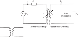
The general symbol for a transformer and the circuit diagram for a typical transformer feeding a load impedance, Z2, are shown in the diagram. In the case of an ideal transformer there is complete coupling between the primary and secondary windings and therefore
where M is the mutual inductance and L1 and L2 are the self-inductances of the two coils. The self-inductances are related to the squares of the numbers of turns, n1, n2, of the two coils by the equation
where n is the turns ratio of the given transformer.
In the ideal case energy dissipation in the core can be ignored and it can be shown that
where Zp is the impedance of the primary circuit and Z2/n2 represents the effect of the secondary circuit on the primary and is known as the reflected impedance. The current in the secondary circuit is I2 and the impedance is Zs. They are given by
From these equations it can be seen that
In practice complete coupling is not achieved and the mutual inductance is given by
and
where k is the coupling coefficient.
Suitable design of the device can optimize the coupling and minimize the energy dissipation: values of k almost equal to unity may be achieved. Energy dissipation is kept to a minimum by winding the coils around laminated cores; the magnetic circuit of the cores is completed by forming them as a yoke. The two coils are sometimes interwound but insulation can be a problem where high voltages are used and they are then wound side by side. Uniformity of the magnetic flux density within the coils can be maintained by using an extra core (a limb) that surrounds the coils.
The property of voltage transformation is used in the voltage transformer. This can be used as an instrument transformer in order to measure voltages. The primary winding is connected in parallel with the main circuit and the secondary winding connected to a suitable measuring instrument. The voltage transformer may also be used as a power transformer in order to supply electrical power at a predetermined voltage to a circuit. The primary winding is usually connected to the electrical mains supply. The secondary winding consists either of several windings or of one winding with several tappings in order to supply different magnitudes of voltage or to supply more than one circuit. The transformer is described as step-up or step-down according to whether the secondary voltage is respectively greater or less than the primary voltage.
The current transformer utilizes the current transformation property and is most often used as an instrument transformer. The primary winding is connected in series with the main circuit and the secondary to the appropriate measuring instrument. Current transformers are also used to operate protective relays in order to prevent the current in the main circuit rising above a predetermined value.
See also autotransformer; core-type transformer; shell-type transformer.

General symbol (left) and equivalent circuit of a transformer
http://www.explainthatstuff.com/transformers.html An introduction to transformers, with useful links
- strontium star
- strontium sulphate
- strophic
- Strophomenida
- strophomenids
- Stroustrup, Bjarne (1950–)
- structural adjustment
- structural break
- structural consequence relation
- structural contour map
- adapical
- adaptation
- adaptive channel allocation
- adaptive compression
- adaptive control system
- adaptive-control system
- adaptive delta modulation
- adaptive differential pulse code modulation
- adaptive environmental management
- adaptive equalizer
- adaptive expectations
- adaptive Huffman coding
- adaptive immunity
- adaptive interface
- adaptive logic