A digraph in which every arc is assigned a weight (normally some non-negative number). In some applications, something may be thought of as flowing or being transported between the vertices of a network, with the weight of each arc giving its capacity. In some other cases, the vertices of a network may represent steps in a process and the weight of the arc joining u and v may give the time that must elapse between step u and step v.
A graphical representation of a problem by means of nodes connected by arcs of varying length or capacity. The arcs are usually directed. Examples include finding the shortest path, consisting of a connected set of arcs, that joins all the nodes, the Chinese postman problem, and the travelling salesman problem. In some applications it is the nodes that have associated values. See also critical path analysis; network flow problem; reliability theory.
1. In communications, a rather loosely defined term applied to a system that consists of terminals, nodes, and interconnection media that can include lines or trunks, satellites, microwave, medium- and long-wave radio, etc. In general, a network is a collection of resources used to establish and switch communication paths between its terminals. A given network may be classified as a local area network, a metropolitan area network, or a wide area network, the differences lying as much in their style of organization as in their technology or geographical or physical size. Networks and servers have now largely replaced centralized mainframe computers in most applications. See also message switching, network architecture, network delay, packet switching.
2. In electronic circuitry, an interconnection of various electrical elements. A passive network contains no active (amplifying or switching) elements such as transistors; a linear network is a passive network that contains no nonlinear elements such as diodes.
3. (net) In mathematics, a connected directed graph that contains no cycles. Interconnections involving objects such as telephones, logic gates, or computers could be represented using a connected but not necessarily directed graph.
A collection of computers connected by transmission media.
1. In electronics, a number of impedances connected together to form a system that consists of a set of interrelated circuits and that performs specific functions. The behaviour of the network depends on the values of the components, such as the resistances, capacitances, and inductances, from which it is formed and the manner in which they are interconnected. The values of the components are termed the network parameters or network constants. The nomenclature of networks describes either the type of component, the method of interconnection, or the expected behaviour of the network.
Networks are described as resistive, resistance-capacitance (R-C), inductance-capacitance (L-C), inductance (L) networks, etc., depending on their components.
• Lattice networks have the input and output terminals at a junction between two or more conductors (Fig. a); a bridge network is a particular type of lattice network (Fig. b).
• Series networks and parallel networks have their elements connected in series and in parallel, respectively.
• Linear networks have a linear relationship between the voltages and currents; otherwise they are nonlinear.
• Bilateral networks conduct in both directions whereas those that conduct in only one direction are unilateral.
• Passive networks contain no energy source or sink other than normal ohmic losses; those that do contain an energy source or sink are active.
• All-pass networks attenuate all frequencies equally; other networks are described according to their frequency response (see filter).
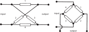
(a) Lattice network (b) Bridge network
A point within a network at which three or more of the elements are joined is termed a node (or branch point); points 1–8 in Fig. c are nodes. A conducting path between two such points is termed a branch (1–2, 3–4, etc., in Fig. c). A voltage at a point in the network measured relative to the voltage at a designated node is termed a node voltage. A closed conducting loop in the network (e.g. 1, 3, 7, 5, 1) forms a mesh contour, and the portion of the network bounded by it is termed a mesh. Any branch that is common to two or more meshes is a mutual branch (e.g. 5–6). Two branches of a network are said to be conjugate if an e.m.f. in one of them does not produce a current in the other. The currents circulating in the meshes are known as mesh currents.
The behaviour of a network may be analysed by applying Kirchhoff’s laws to each mesh in the network in turn; both the real and imaginary parts of the complex impedances involved must be satisfied simultaneously. For a large network containing many meshes, as with many types of filter network, this method is very cumbersome. An alternative is to apply Thévenin’s theorem or Norton’s theorem to a linear network; these theorems however cannot be applied to nonlinear networks.
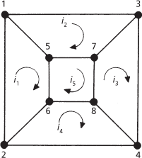
(c) Conducting paths of a network
Analysis of linear networks can most usefully be done by considering the network as a two-port network and deriving sets of equations relating the currents, voltages, and impedances at the input and output; this is known as two-port analysis. Fig. d shows a passive two-port network with an input source consisting of a voltage generator Vs of internal impedance Zs. Fig. e shows an active two-port network presenting an input impedance z1 to the input source Vs of internal impedance Zs, and appearing as a current generator gmv1 shunted by a resistance r0 and producing a voltage v2 in the output circuit (gm being the transconductance).
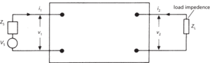
(d) Passive two-port network
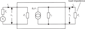
(e) Active two-port network
Three different sets of equations can be written down: the impedance equations, the admittance equations, and derived from these the hybrid equations. The impedance equations can be written in the form of a matrix:
Equivalent matrices can be written for the hybrid and admittance equations. The constants in these equations are known as z, h, and y parameters, respectively, or collectively as two-port parameters. Three-terminal devices, such as transistors, can be represented as two-port networks that have two terminals joined together (see transistor parameters).
In the case of nonlinear networks the matrix equations are only true for small changes of current and voltage. In such cases the two-port parameters are termed small-signal parameters and are quantities that change value according to the operating conditions of the device.
The input and output impedances of a network, v1/i1 and v2/i2, can be calculated from the matrix equations; it can be shown that v1/i1 depends on the load impedance ZL connected to the output and conversely that v2/i2 depends on the impedance Zs of the source connected to the input.
The driving-point impedance is the impedance presented at a pair of terminals of a network of four or more terminals, under designated conditions at the other pair(s) of terminals. In the limiting case, for a two-port network, if the input (or output) is open circuit, the output (or input) impedance is the open-circuit impedance. The other limiting case is when the input (or output) is a short circuit in which case the output (or input) impedance is the short-circuit impedance. The quantities v2/i1 and v1/i2 are the transimpedances of the network under open-circuit conditions, i.e. when i2 = 0 and i1 = 0, respectively.
2. In communications, a collection of resources used by a group of users to exchange information. In a local area network (LAN), users generally belong to a single organization located on a single site or a small number of nearby sites. A wide area network (WAN) is also usually operated by a single organization but communications are over large distances. Communication paths in a network are established and switched between computer terminals following agreed procedures known as protocols. The communication lines may include cables, optical fibres, phone lines, or radio links. These communication lines are interconnected at points known as nodes. The nodal device may be an electrical interface or a computer. See also digital communications; bus network; ring network; star network.
A system of interconnecting routes which allows movement from one centre to the others. Most networks are made up of nodes (vertices), which are the junctions and terminals, and links (edges), which are the routes or services which connect them. ‘Networks constitute the new social morphology of our societies, and the diffusion of networking logic substantially modifies the operation and outcomes in the processes of production, experience, power and culture’ (M. Castells 1996). Dicken (2004) TIBG 29, 1 describes situated networks as a generic form of social organization. Brown et al. (2008) GaWC Res. Bul. 236 see the world economy as based upon economic nodes connected as chains/networks. See Glückler (2007) J. Econ. Geog. 7, 5 on economic geography and the evolution of networks.
Network connectivity is the extent to which movement is possible between points on a network—cities’ housing firms with high service values will record large measures of network connectivity. Taylor et al. (2002) ESRC attempt to measure the global network connectivity of cities. See also Taylor and Catalano (2001) GaWC Research Paper 61 for global, and banking, network connectivity.
1. A group of consumers for whom the utility derived from the consumption of certain goods or services increases as additional consumers purchase the same goods and services. Networks emerge if these particular goods or services have little or no value in isolation, but generate more value when more consumers use the same goods and services. A market characterized by such properties is called a network market in which there exist positive consumption externalities termed network externalities. A typical example of a network market is telecommunications.
2. A model of the interconnections within a set of consumers or firms. A network is described by a set of links that determine which consumers or firms are connected. As examples, connections can describe which consumers know each other, or which consumers are customers of a firm. Networks can be used to describe any economic or social situation in which there is a structure to the interaction of individuals. See also private network; public network.
- mineral soil
- minette
- minette ironstone
- Ming
- Minghuang (684–762)
- mingle
- minicell
- minicomputer
- mini DIN connector
- minimal algebra
- minimal cut vector; minimal path vector
- minimal element
- minimalism
- minimal machine
- minimal medium
- minimal polynomial(of an algebraic number)
- minimal polynomial(of a square matrix)
- minimal state
- minimal supersymmetric standard model
- minimal surface
- minimax
- minimax; minimum
- minimax procedure
- minimax regret
- minimax strategy