1. (in chemistry) A device for separating solid particles from a liquid or gas. The simplest laboratory filter for liquids is a funnel in which a cone of paper (filter paper) is placed. Special containers with a porous base of sintered glass are also used.
2. (in physics) A device placed in the path of a beam of radiation to alter its frequency distribution. For example, a plane pigmented piece of glass may be placed over a camera lens to alter the relative intensity of the component wavelengths of the beam entering the camera.
3. (in electronics) An electrical network that transmits signals within a certain frequency range but attenuates other frequencies.
1. An optical component through which light of only certain restricted wavelengths can pass, the other wavelengths being blocked. Two types are in general use: glass filters and interference filters. Glass filters are made from disks of coloured glass. Interference filters are made from multiple layers or coatings on glass which cause interference between light waves, allowing only a limited range of wavelengths to pass. Glass filters are mostly used for broad-band photometry, while interference filters are used for intermediate-band and narrow-band photometry. The bandwidth of the filters (i.e. the range of wavelengths which they pass) lies in the ranges 30–100 nm for broad-band, 10–30 nm for intermediate-band, and 3–10 nm for narrow-band photometry.
2. An electronic device designed to transmit a certain range of frequencies and reject others. A low-pass filter transmits below a certain cut-off frequency; a high-pass filter transmits above a cutoff frequency; a bandpass filter transmits between two cutoff frequencies; a notch filter is designed to reject a narrow band of frequencies.
A procedure that converts one time series into another. A simple example is a moving average, which, because it is a linear combination of the terms in the time series, is described as a linear filter. A filter that removes short-term random fluctuations is called a low-pass filter, and one that removes long-term fluctuations is called a high-pass filter.
A device for separating solid particles from a liquid or gas. The simplest laboratory filter for liquids is a funnel in which a cone of paper (filter paper) is placed. Special containers with a porous base of sintered glass are also used. See also Gooch crucible.
A device used to remove and separate particles from gases or liquids. The particles may be undesirable such as contaminants in an air stream as in the case of ventilation, or as extraneous material in food processing. The size of the pores or mesh size of a filter determines the size of the particles retained. Filters are classified as roughing, medium efficiency, high efficiency, ultra-high efficiency, and absolute. Strainers are a type of coarse filter. Filter cloths are used to retain particles from liquids and are typically made from cotton, glass, and synthetic woven fibres or mats. See filter press.
1. A program that processes a sequential stream of text, carrying out some simple transformation, e.g. condensing multiple spaces to single spaces, counting words, etc. Powerful effects can be created by connecting a series of filters in a pipeline, where each filter takes as its input the output produced by its predecessor.
2. A simple electric circuit or some more complicated device used in the process of filtering. See band-pass filter, high-pass filter, low-pass filter.
3. A set of conditions applied to data so that only certain conforming items are displayed or processed.
A general term used to describe software which examines some content and prevents it from reaching its destination, filters are based on a number of rules stored in a script or a profile. An example of such a filter is one which detects spam emails and rejects them.
An electrical network that will transmit signals with frequencies within certain designated ranges (pass bands) and reject or attenuate signals of other frequencies (stop or attenuation bands). The frequencies that separate the pass and stop bands are the cut-off frequencies, which have the symbols fc if there is only one cut-off frequency or f1 and f2 if more than one. Filters are classified according to the ranges of their pass or stop bands as low-pass, high-pass, band-pass and band-stop filters; the four main classifications with their corresponding frequency limits are shown in the table.
Type of filter
Pass band(s)
Stop band(s)
low pass
0 – fc
fc – ∞
high pass
fc – ∞
0 – fc
band pass
f1 – f2
0 – f1, f2 – ∞
band stop
0 – f1, f2 – ∞
f1 – f2
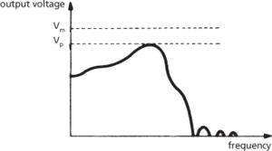
An ideal filter would transmit the pass band without attenuation and completely suppress the stop band, with a sharp cut-off profile. Practical filters however do attenuate the pass band, due to absorption, reflection, or radiation, which results in loss of signal power; neither do they completely suppress the stop bands. A typical curve of output voltage with frequency is shown in Fig. a for a simple low-pass filter: Vp is the peak voltage and Vm is the maximum voltage of an ideal filter. The filter attenuation is defined as the loss in signal power in decibels or nepers through the filter; the filter discrimination is the difference between the minimum value of insertion loss in a stop band and the maximum value in a pass band.

(a) Low-pass filter output
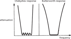
The components of a practical filter may be arranged to give the desired output curve. For example, Chebyshev and Butterworth filters are band-pass filters with different output characteristics (Fig. b). Butterworth filters have a flat response in the pass band whereas Chebyshev filters have some variation of the residual response in the pass band but have a more rapid increase of attenuation giving a sharper cut-off profile.

(b) Band-pass filters
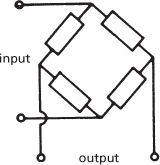
Filters are active or passive according to their components. Active filters contain active components, such as operational amplifiers, that introduce some gain into the signal combined with suitable R-C feedback circuits to give them the desired frequency-response characteristic. Most passive filter networks are constructed from impedances arranged in shunt and in parallel (L-C networks). Two basic arrangements are used: π-sections and T-sections (Fig. c). Composite networks are built up from these basic sections and the arrangement is termed a ladder network because of the alternation of shunt and parallel sections. Another type of configuration is the lattice filter in which the impedance elements are arranged in a bridge network (Fig. d).

(c) Passive filters

(d) Lattice filter
The bandwidth of a band-pass or band-stop filter is the difference in hertz between two particular frequencies whose geometric mean equals that of the geometric mid-frequency of the pass or stop band. Frequencies exhibiting a particular characteristic, such as the point at which the response is three decibels below the peak value, are usually chosen.
1. A device for removing unwanted components from water. Coarse material may be recovered by the use of simple mesh sieves, but finer material and certain pollutants may require the use of other filters, e.g. of activated carbon or sand.
2. To discriminate against a portion of information entering a device (the filter), typically by removing unwanted noise or isolating specific parts of the information (e.g. separating high-frequency from low-frequency data). Filters usually operate within the frequency domain although others exist (e.g. the velocity filter). Frequency filters have the disadvantage of invariably distorting the signal pulse shape, lengthening the pulse and so causing a phase shift, and displacing peaks and troughs in time. Linear filtering is known as convolution. See also aliasing; band filter; spatial-frequency filter; wiener filter.
- physical double
- physical explosion
- physical geography
- physicalism
- physical layer
- physical libration
- physical map((in genetics))
- physical medium
- physical quality of life index
- physical units
- physician-assisted suicide
- physico-theological argument
- physico-theology
- Dolgellian
- doline
- dollar
- dollar diplomacy
- dollarization
- dollar standard
- Dollfuss, Engelbert (1892–1934)
- Dollo, Louis Antoine Marie Joseph (1857–1931)
- Dollond, John
- Dollond, John (1706–61)
- Dollo’s law
- Doll, Sir (1912–2005)