A high-quality sound-reproduction system that uses light to detect audio signals encoded by digital recording on a 120 mm metal compact disc (CD). A CD system differs from other sound-reproduction systems in that there is no physical contact between the pick-up and the recording, thus minimizing wear; the information layer is buried below the surface of the disc, which minimizes errors in the sound reproduction due to dust or other marks on the surface. The original analogue audio information is sampled and quantized using an analogue-to-digital converter (see sampling; quantization), and the coded digital data is then recorded. The audio signals are encoded in the form of a spiral track of minute pits that are impressed into one surface of the disc at the time of manufacture; the narrow track spirals outwards from the centre of the CD. For playback, the disc is loaded into a CD player and secured to a spindle on which it can be rotated. The system operates by using CLV, i.e. a constant linear velocity of track relative to pick-up so the rotational speed is a function of the radius of the track, and varies as the pick-up moves across the disc.
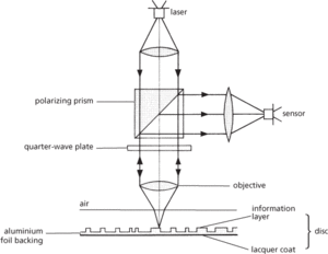
The essential component of the pick-up is a small low-power semiconductor laser continuously emitting coherent light, which is focused as a small spot onto the reflecting surface of the disc (Fig. a). Reflected light from the disc is modulated by the code impressed on the track, and is then detected by a phototransistor to produce an electric signal corresponding to the recorded information. These signals are then converted back into audio signals. In order to maintain high-quality sound output very sophisticated error control systems are required to ensure that focusing and tracking integrity are maintained, and that the disc is rotated at the correct speed.
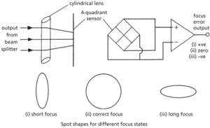
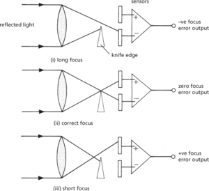
The resolution of the pick-up depends critically on the spot size: disc warp and irregularities in the thickness will cause an out of focus condition with resulting loss of sound quality and crosstalk from adjacent tracks. A focus servo system is used to move the lens along the optical axis to keep the spot in focus. The focus error signal is generated using one of two main methods. The cylindrical lens method (Fig. b) has a cylindrical lens placed between the beam splitter and the photodetector. The image reaching the sensor will be circular only when the focus is correct, otherwise it becomes an ellipse whose aspect ratio changes as a function of the state of focus. The sensor is split into four quadrants, connected as shown. The focus error signal is generated from the difference between the outputs, and the data signal is the sum of all four outputs. The knife edge and dual prism methods are the second means of generating the focus error signal. They also require split sensors, mounted beyond the focal point. In the knife edge method (Fig. c) a knife edge is positioned at the point of correct focus and the outputs of the two sensors compared to produce the focus error signal. The dual prism method is essentially similar but replaces the knife edge with a dual prism and three sensors.

(a) Essential components of the optical pick-up of a compact disc system

(b) Cylindrical lens method

(c) Knife edge method
Accurate tracking of the beam is also required, and a track-following servo system is used to keep the spot centralized on the track. Tracking errors arise from various sources: the track separation is smaller than the accuracy to which either the player spindle or the central hole in the disc can be manufactured; a warped disc will be tilted relative to the beam at the surface and the apparent position of the track relative to the pick-up will constantly change as the disc rotates; external forces outside the CD player can induce vibrations that tend to disturb the tracking.
During the recording process, the audio signal is sampled at a rate of 44.1 kHz and a form of pulse code modulation is used to convert the samples into a coded form which modulates a high-frequency clock pulse. The clock operates at 4.3218 MHz. The majority of compact disc systems use eight to fourteen modulation (EFM) in which any combination of eight real data bits is uniquely described by a pattern of 14 channel bits. A further three packing bits are interposed between each pattern to separate them. The digital modulation code produced is known as the channel code. The transitions between ones and zeros of the channel code are used to produce bump edges in the surface of a master disc. The bumps are translated into pits when the CD impressions are manufactured. The edges are detected by the optical system in the CD player to produce corresponding transitions in the replay signal. The replay signal must then be accurately decoded to produce the audio output.
The first step in the process is to compare the detected signal with a reference voltage. This process is termed slicing. This recreates the binary channel code. A phase-locked loop running at the clock frequency counts the number of clock pulses between transitions and recreates the patterns of 14 channel bits. These are decoded back to data bytes using a ROM or array of gates. The data bytes are then fed through a digital-to-analogue converter to recreate the original audio signals. The packing bits are used to determine the start position of each 14 bit pattern, and a regular synchronizing pattern is also added to lock the readout circuits to the symbol boundaries.
The actual layout of the coded data on the disc is much more complex than a simple sequential layout in order to allow for errors in the readout data to be corrected, and to reduce noise due to contamination and surface scratches. The audio data is coded into data blocks or frames of 33 patterns, each following a synchronization pattern. The audio samples use 24 of the 33 bytes, and 8 of the bytes are redundancy bytes forming the basis of the error correction system; the first byte of each data block is used as a subcode to produce a running time display. The sampling rate of 44.1 kHz, producing 16-bit words in left and right channels, results in 176.4 Kbytes of audio data per second.
The error correction system has to deal with errors due to scratches, which can affect many bits of code (burst errors), and random errors caused by imperfect pressing of a bump edge. This latter can result in the conversion of one pattern into another and therefore up to 8 bits of data can be in error. Extra bits are added to the coded information (redundancy) and can be used to correct damaged data bits when playing back. A code word consists of the total of data and redundant bits. The value of the redundant bits is calculated from the data itself according to a code known as the Reed–Solomon code. The resulting code words are then interleaved within each data frame to reduce the effect of burst errors; a large error causes slight damage to many code words rather than severe damage to one. This system is known as cross-interleave Reed–Solomon code (CIRC). The Reed–Solomon codes used to correct errors are a very powerful tool. Error correction is necessary because the effect of digital errors results in a sound rather like vehicle ignition interference in radio reception and is unacceptable to a listener. The development of compact disc systems has always taken into account that the finished product should not require any particular handling problems. Where data corruption is so bad that the error correction cannot cope, the system contains muting circuits that operate to reduce the gain of the CD player.
- scope
- Scopes case (July 1925)
- scopuli
- scopulus
- score
- score function
- scoria
- scoriaceous
- scoria cone
- scorpion
- scorpionate
- scorpions
- Scorpius
- Scorpius X-1
- Scorpius–Centaurus Association
- Scotch mount
- Scotia Plate
- Scotism
- Scotland
- Scotland Yard
- scotopic vision
- Scots
- Scott consequence relation
- Scott, David Randolph (1932– )
- Scottish Martyrs