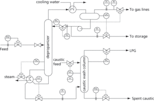
A schematic representation of the interconnecting pipelines and control systems for a process or part of a process (see Fig. 38 for an example). Using a standard set of symbols for process equipment and controllers, it includes the layout of branches, reducers, valves, equipment, instrumentation, and control interlocks. They also include process equipment names and numbers; process piping including sizes and identification; valves and their identification; flow directions, instrumentation, and designations; vents, drains, samplings lines, and flush lines. P&IDs are used to operate the process system as well as being used in plant maintenance and process modifications. At the design stage, they are useful in carrying out safety and operations investigations such as HAZOP. See Appendix 4.

Fig. 38 Piping and instrumentation diagram
- Euramerica
- Eurasian Plate
- EURECA
- EUREKA
- Eureka Rebellion (1854)
- euro
- Eurobarometer
- eurobond
- eurocurrency
- eurodollars
- euroland
- euromarket
- EuroMir
- Europa
- Europa rocket
- Europe
- Europe agreements
- European Aeronautic Defense and Space Company
- European Article Numbering code
- European Astronaut Corps
- European Bank for Reconstruction and Development
- European Central Bank
- European Centre for Medium-Range Weather Forecasts
- European Coal and Steel Community
- European Commission